This diagram consists from standard flowchart symbols, approved by ANSI (American National Standard Institute) for drawing flowcharts. Nevertheless, once you start flowcharting, you’ll love its simplicity and efficiency. You can find flowchart symbols, shapes, stencils and icons easily on the Internet, but it might take time to systematize this information. Flowchart symbols, shapes, stencils and icons → When thinking about data visualization, one of the first tools that comes to mind is a flowchart design. To connect elements using this tool, drag the connector from one connect dot to another.You can use Layers to place connections on different layers.įlowchart design.


To open the menu select an object and click the button in the upper right corner of the object. Such objects can be edited by using the Action button menu.

Transistor symbol how to#
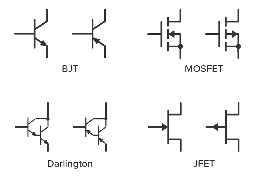
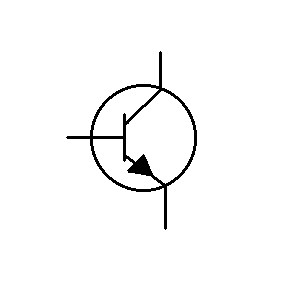
How to Create an Circuit Diagram Using MOSFET Library The term "metal" is historically used for the gate material, even though now it is usually highly doped polysilicon or some other nonmetal. The generic term for the "dielectric" is "gate dielectric", since the dielectric lies directly below the gate electrode and above the channel of the MISFET. The insulator in a MISFET is a dielectric which can be silicon dioxide (in a MOSFET), but other materials can also be employed. All MOSFETs are MISFETs, but not all MISFETs are MOSFETs. "MISFET" is a more general term than "MOSFET" and a synonym to "insulated gate field-effect transistor" (IGFET). The following table lists some MOSFET electrical symbols in our electrical diagram software.Ī MISFET is a metal–insulator (electrical)–semiconductor field-effect transistor. Electrical symbols are used to represent various electrical and electronic devices in a schematic diagram of an electrical or electronic circuit.

Most of the electrical symbols can be changed in their appearance, styles and colors according to users' requirements.
Transistor symbol software#
You can simply and quickly drop the ready-to-use objects from libraries into your document to create the electrical diagram.Įlectrical diagram software will assist you in drawing your electrical diagrams with minimal effort and makes it very easy for beginners.Įlectrical symbols and smart connectors help present your electrical drawings, electrical schematic, wiring diagrams and blue prints. For this purpose you can use the Electrical Engineering solution from the "Engineering" area of ConceptDraw Solution Park.Įlectrical Engineering Solution for ConceptDraw DIAGRAM provides the stencils libraries of ready-to-use predesigned 926 vector symbols, templates and samples that make your electrical drawing quick, easy and effective.Ģ6 libraries of the Electrical Engineering Solution of ConceptDraw DIAGRAM make your electrical diagramming simple, efficient, and effective.
Transistor symbol professional#
The MOSFET is by far the most common transistor in both digital and analog circuits, though the bipolar junction transistor was at one time much more common.ĬonceptDraw DIAGRAM is a powerful software for creating professional looking electrical diagram quick and easy. Because these two terminals are normally connected to each other (short-circuited) internally, only three terminals appear in electrical diagrams. The metal–oxide–semiconductor field-effect transistor (MOSFET, MOS-FET, or MOS FET) is a type of transistor used for amplifying or switching electronic signals.Īlthough the MOSFET is a four-terminal device with source (S), gate (G), drain (D), and body (B) terminals, the body (or substrate) of the MOSFET is often connected to the source terminal, making it a three-terminal device like other field-effect transistors.


 0 kommentar(er)
